On certain AstonDB11 vehicles an electrostatic discharge (ESD), when combined with a damaged steering column control module clock spring and an insufficient grounding of the steering column upper, may lead to an inadvertent deployment of the driver airbag, which can increase the risk of injury and a crash. This instructions show how to install a contact bridge and a contact spring to the steering column. These components will remove the static charge from the steering wheel.To correct this problem you must install two grounding components to the steering column.
This Workshop Procedure has two parts: [where applicable]
- Part A– Examine steering column
- Part B– Install steering column grounds
Part A – Examine steering column
Note: Part A of the procedure that follows is for vehicles from L02866 thru L03917 only.
1.Move the hush panel to get access to the screw that attaches the lower duct to the instrument panel.
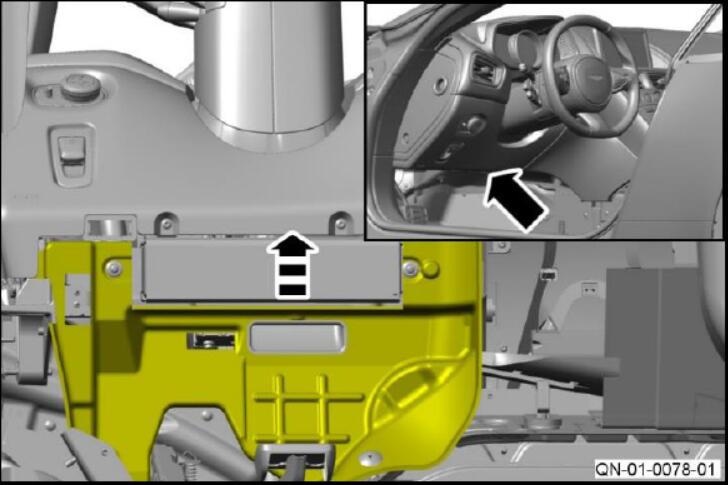
2.Remove the screw that attaches the lower duct to the IP.
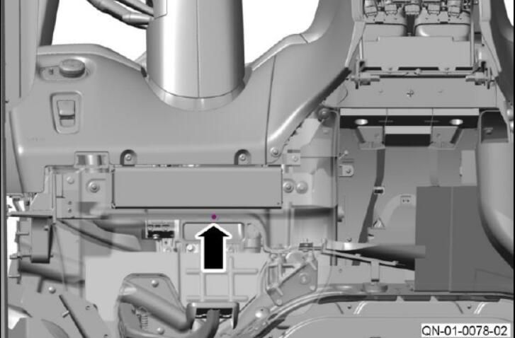
3.Move the vent duct to get access to the steering Column
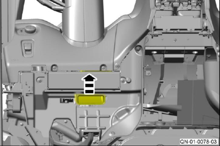
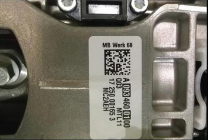
4.Do a check of the component number on the label
- If the steering column is Q01 or Q02,photograph the label and do Part B after PartA is complete.
- If the steering column is Q03 or higher, nomore work is necessary after Part A iscomplete.
5.Move the vent duct to its original position
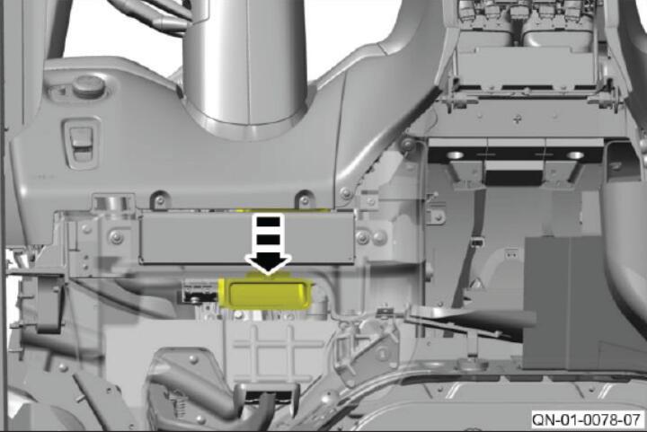
6.Install and tighten the screw that attaches the lower duct to the IP
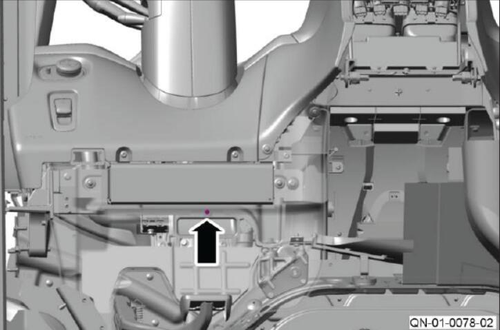
Part B – Install steering column grounds
Note: Part B of the procedure that follows is for all DB11 vehicles to L02865. Part B is also for DB11 vehicles from L02866 thru L03917 with Q01 or Q02 steering columns.
1.Move the steering column to its lowest position.
2.Remove the top and bottom shroud assembly for the steering column (refer to Workshop Manual Procedure 11.04.DB).
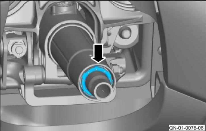
3.Install the contact spring onto the circular casting on steering column
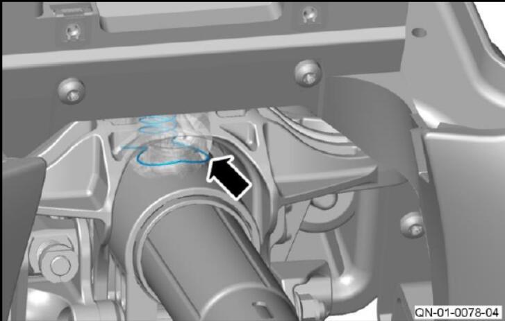
4.The contact spring must be installed so that it touches the circular casting on the steering column
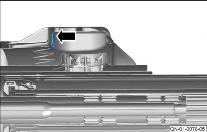
5.Install the contact bridge onto the steering column
Note: The contact bridge must touch the outer steering column shaft.
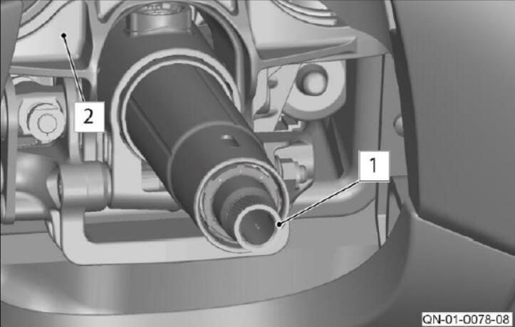
6.Use a multi-meter to measure the resistance between the inner column (1) and the steering column casing (2)
- If the resistance is below 3 ohms go to step 7.
- If the resistance is above 3 ohms, make sure thecomponents installed in steps 3 thru 5 are installed correctly.
Note: If the resistance is still above 3 ohms, contact AMTech.
Install the top and bottom shroud assembly for the steering column (refer to Workshop Manual Procedure 11.04.DB).
Warranty Data
Make sure that you submit your claim in less than 24 hours after the work is completed. The records of your claims are used in the reporting process for the Safety Recall Action that Aston Martin need to submit to the National Highway
Note: If part B of the workshop procedure is necessary you must send the photograph of the label with your claim.
Save the photo in the format “Dealer Name – RA-01-1048 – ******” (6 Digit Chassis No)
Use the same format in the title of an email and send it to [email protected]
Please be aware that Warranty claims for installation of the contact spring and contact bridge parts may be charged back if a photograph is not received.