This illustration show you guide on how to remove and install 1-BOX aftertreatment control module for Detroit Diesel GHG17 heavy duty engine.
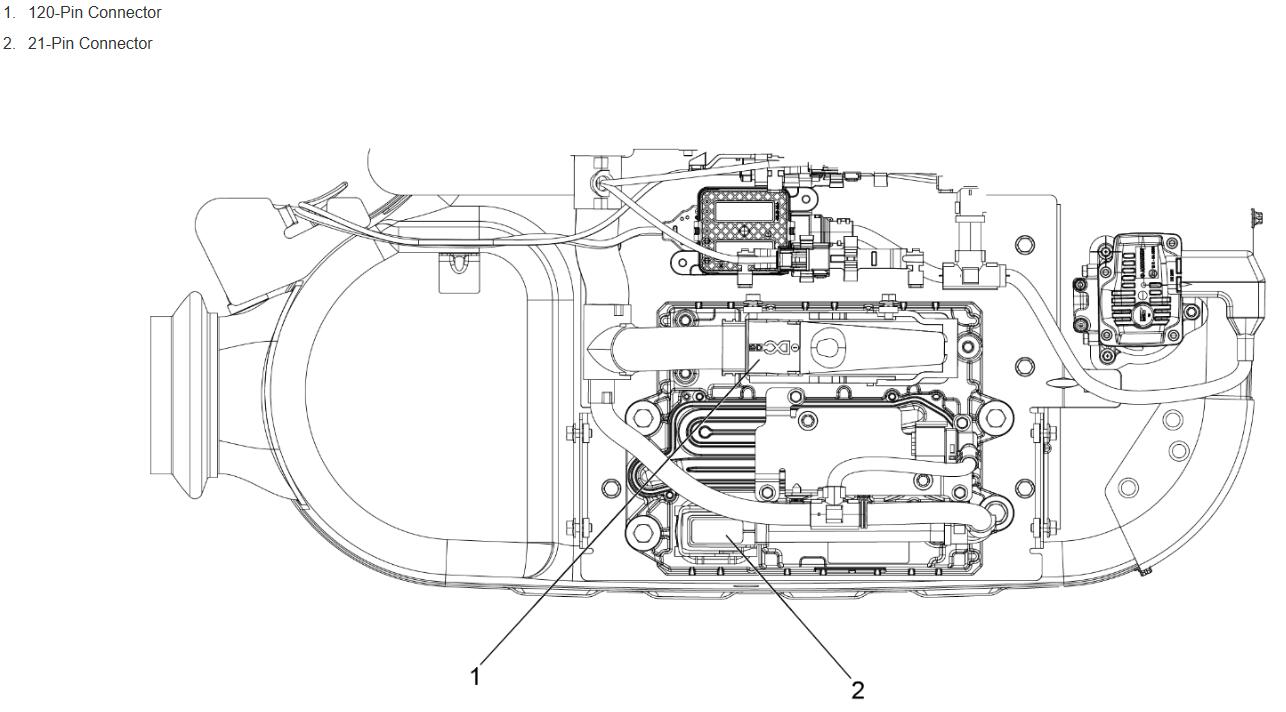
Aftertreatment Control Module (ACM) controls all aftertreatment functions. It is mounted on the 1-BOX™ configuration. Temperature, pressure, and NOx sensors connect to the ACM in addition to aftertreatment components. The ACM uses the inputs from the sensors to control the aftertreatment systems. Vehicle electrical harnesses run throughout the vehicle to connect the ACM to all aftertreatment components and sensors.
Related Contents:
2024.06 Detroit Diesel Diagnostic Link DDDL 8.20 8.09 Free Download
Procedures:
Removal of the 1-BOX™ Aftertreatment Control Module
Remove as follows:
Note : The Aftertreatment Control Module (ACM) is mounted on the rear of the 1-BOX assembly.
1 Shut off engine and apply the parking brake, chock the wheels, and perform any other applicable safety steps.
CAUTION
ELECTRICAL SHOCK
To avoid injury from electrical shock, use care when connecting battery cables. The magnetic switch studs are at battery voltage.
2 Disconnect the batteries. Refer to Original Equipment Manufacturer (OEM) procedures.
3 If necessary, remove the passenger side fairing. Refer to OEM procedures.
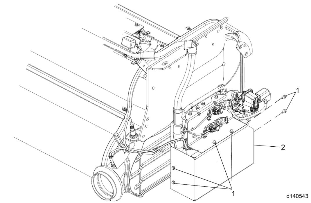
4 Remove the lower ACM cover mounting bolts (1) and remove the cover (2).
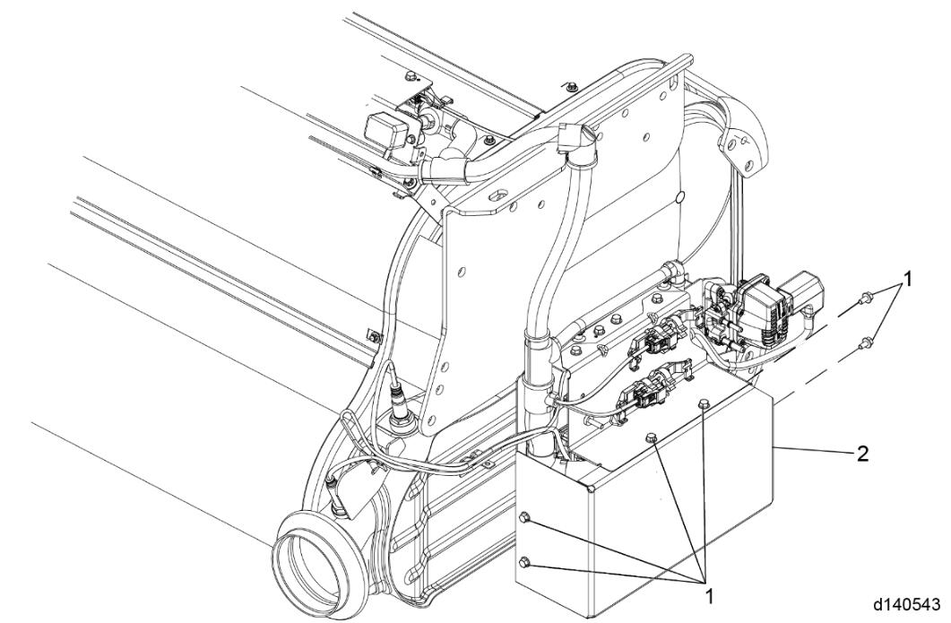
5 Note the location of the zip ties mounting the ATS harness to the ACM.
6 Remove the zip ties mounting the Aftertreatment System (ATS) harness to the ACM.
7 Release latch on harness connector to remove the 21-pin (1) and the 120-pin (4) electrical connectors from the ACM.
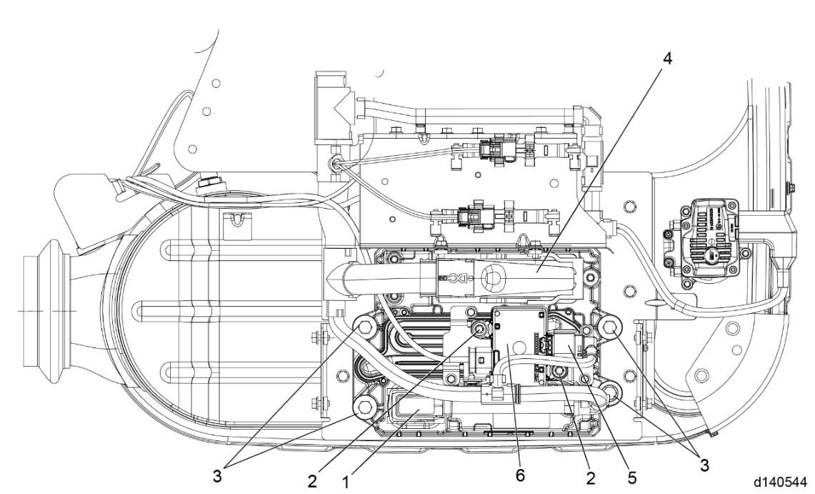
8 Disconnect the Soot Sensor Control Unit (SCU) electrical connector (5).
9 Remove the Soot SCU mounting bolts (2) and remove the SCU (6).
Note : If replacing the ACM, remove the Soot SCU, mounting bracket and bolts.
10 Remove the four mounting bolts (3) securing the ACM; remove ACM along with the isolators.
Installation of the 1-BOX™ Aftertreatment Control Module
Install as follows:
Install the Aftertreatment Control Module (ACM) with four mounting bolts (3) and eight isolators. Torque the bolts to 15 N·m (11 lb·ft).
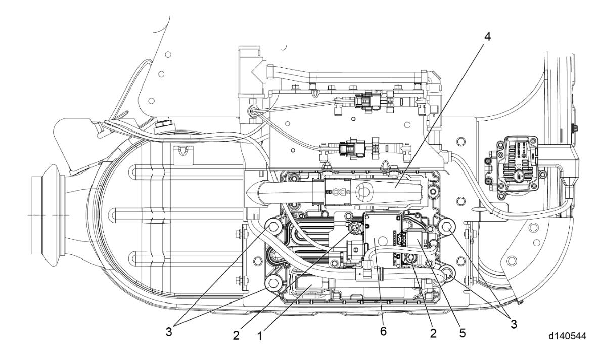
Note : If replacing the ACM, install the Soot Sensor Control Unit (SCU) mounting bracket with new bolts.
2 Install the Soot SCU (6) and torque the mounting bolts (2) to 12 N·m (9 lb·ft).
3 Connect the Soot SCU electrical connector (5).
4 Connect the 21-pin (1) and 120-pin (4) electrical connectors to the ACM. Close and lock the latch on the connectors.
5 Install the zip ties that mount the Aftertreatment System (ATS) harness to the ACM.
6 Install the lower ACM cover (2) with the six mounting bolts (1). See graphic below. Torque the bolts to 10 N·m (7 lb·ft).
CAUTION
ELECTRICAL SHOCK
To avoid injury from electrical shock, use care when connecting battery cables. The magnetic switch studs are at battery voltage.
7 Connect the batteries. Refer to OEM procedures.
8 If removed, install the passenger side fairing. Refer to Original Equipment Manufacturer (OEM) procedures.
9 Is the MCM being installed a replacement MCM?
9a Yes; using DiagnosticLink ® , program the MCM to the correct configuration. After programming, perform an Accumulated Fuel Mass Sync. For more information, reft to the DiagnosticLink help menu. Afterwards, Go to step 10.
9b No; Go to step 10.
10 Turn the ignition ON (key ON, engine OFF). Observe DiagnosticLink® for any diagnostic code(s). If any code(s) are logged, refer to the proper code diagnostics.
More repair cases for Detroit Diesel engines,please refer to:Detroit Diesel Engine Repair