This instruction show you guide on how to remove,install and inspect cylinder head for Linde HT30D forklift truck.
Preparations:
2023 Linde Service Guide LSG 5.2.2 U0278 and 5.1.2 Free Download
Procedures:
Cylinder Head Components
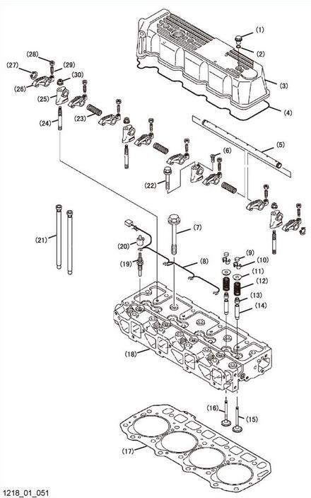
1 Valve cover nut
2 Valve cover nut O – ring
3 Valve cover
4 Valve cover gasket
5 Rocker arm shaft
6 Rocker arm shaft retaining screw
7 Cylinder head bolt
8 Glow plug harness
9 Valve cap
10 Valve keepers
11 Spring retainer
12 Valve spring
13 Valve stem seal
14 Valve guide
15 Intake valve
16 Exhaust valve
17 Cylinder head gasket
18 Cylinder head
19 Glow plug
20 Glow plug cover
21 Push rod
22 Support bracket bolt
23 Rocker arm shaft spring
24 Support bracket stud
25 Support bracket
26 Rocker arm
27 Rocker arm shaft retaining ring
28 Valve adjusting screw lock nut
29 Valve adjusting screw
30 Support bracket nut
Removal of cylinder head
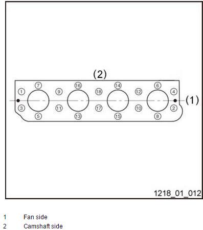
➢Loosen the cylinder head bolts following the sequence shown.
➢Remove the cylinder head bolts (1)
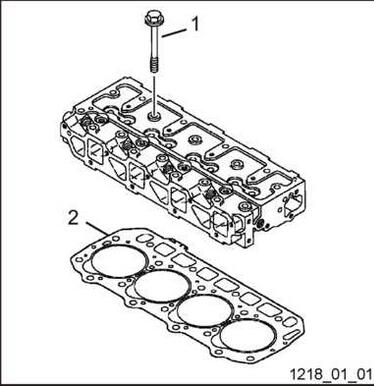
Lift the cylinder head away from the cylinder block. Discard the cylinder head gasket (2) .Position the cylinder head on the work bench to prevent damage to the combustion surface.
Assembly of cylinder head
Carefully clean both the combustion surface of the cylinder head and the top surface of the cylinder block.Then place a new cylinder head gasket (2) on the cylinder block.
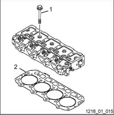
Position the cylinder head on the cylinder head gasket.
➢Lightly oil the threads of the cylinder head bolts (1) .Torque the bolts in steps to the specified torque in table following the sequence.
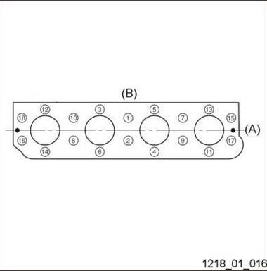
A: Fan side
B: Camshaft side
First Step 49-58.8 N.m
Second Step 103.1-112.9 N.m
➢Insert the push rods in their respective positions.
Inspection of cylinder head
Cylinder head distortion
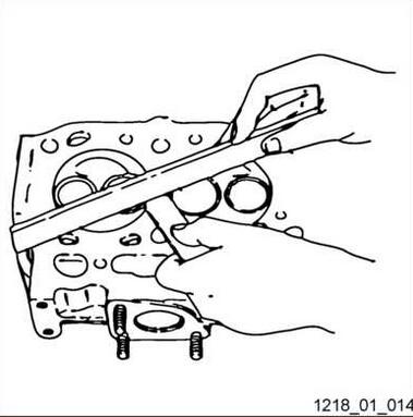
Place the cylinder head flat and inverted (combustion side up) on the bench . Use a straight edge and feeler gauge to measure the amount of cylinder head distortion .
Inspection Item Standard Limit
Combustion surface distortion (Flatness) 0.05mm or less 0.15 mm