This instruction show you guide on how to remove second tank for CLAAS AXION 960-920 Stage V tractor.
Related Contents:
CLAAS CDS 7.5 Diagnostic Software 2021 2020 Free Download
CLAAS 4 CAN Diagnostic Interface
Claas WebTIC Offline Repair & Service 2024 2015 Free Download
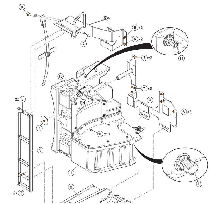
| ID | Value | CCN | Note – Description |
| For unspecified tightening torques, refer to the section entitled: “Tightening torques”. | |||
| 1 | 65 kg | — | Secondary tank |
| 2 | 51 kg | — | Horizontal support |
| 3 | 20 kg | — | Vertical support |
| 4 | 30 kg | — | Right ladder support |
| 5 | 222 ± 44 N.m | — | H M16 x 2.00 nuts |
| 6 | — | H M16 x 2.00 – 35 CL 10.9 bolt | |
| 7 | 72 ± 11 N·m | — | H M12 x 1.75 – 40 CL 8.8 bolt |
| 8 | — | H M12 x 1.75 nuts | |
| 9 | 7 kg | — | Right ladder |
| 10 | 12 ± 2 N.m | — | M8 x 1.25 – 35 CL 10.9 bolt |
| M8 x 1.25 – 30 CL 10.9 bolt | |||
| 11 | 22.5 ± 2.5 N.m | — | Connections |
| 12 | 55 ± 5 N.m | — | Connector |
| 13 | 11 ± 1 N.m | — | Plug |
| 14 | 4 ± 1 N·m | R035 | Fuel level resistor
M5 bolt |
| — | 3.25 ± 0.5 N·m | — | Metal clamps on the tank degassing hoses. |
| — | 5.25 ± 0.75 N·m | — | Metal clamps on the tank connecting hoses. |
Placing the tractor on axle stands.
Risk of death or serious injury.
– Use a reliable axle stand that is rated for the weight of the tractor.
– Carry out this operation on a flat, horizontal and sufficiently firm surface.
– Position the axle stand at the specific lifting point on the tractor.
NOTICE!
Lubricants and fuels end up in the environment.
Environmental pollution
► Collect and store lubricants and fuels in suitable containers and dispose of them properly.
Special tool
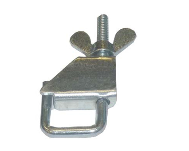
| Special tool – Reference no. | Quantity |
| Hose clamp
No. 00 0181 867 0 |
2 |
Placing the tractor on axle stands.
Risk of death or serious injury.
– Use a reliable axle stand that is rated for the weight of the tractor.
– Carry out this operation on a flat, horizontal and sufficiently firm surface.
– Position the axle stand at the specific lifting point on the tractor.
NOTICE!
Lubricants and fuels end up in the environment.
Environmental pollution
► Collect and store lubricants and fuels in suitable containers and dispose of them properly.
Special tool
► Remove the rear right-hand wheel.
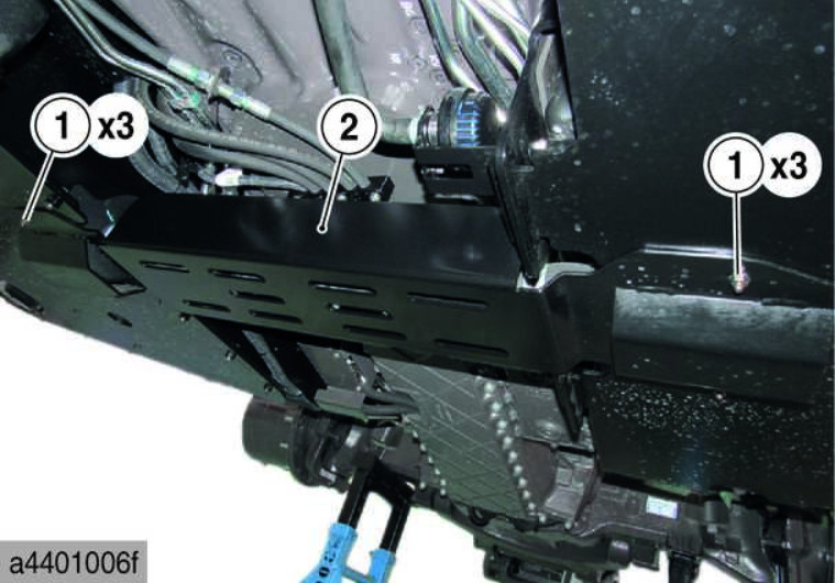
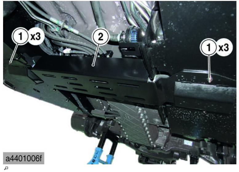
► Undo and remove the nuts (1).
► Remove the protective panel (2).
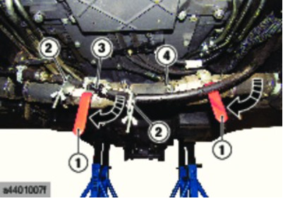
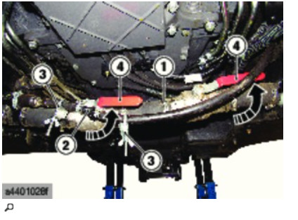
► Fit the special tools (2).
Provide a container to collect the fuel.
► Disconnect the pipe (3).
► Loosen the clamp (4) and disconnect the hose.
► Drain any residual fuel between the two valves.
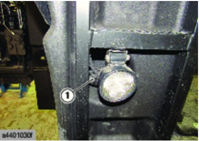
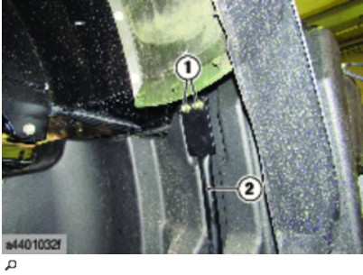
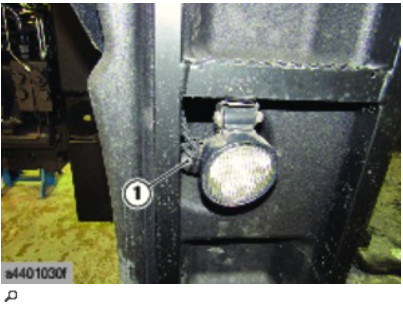
► Disconnect the connector (1) from the work light.
► Detach the wiring harness.
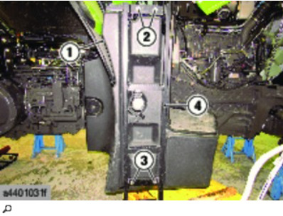
► Remove the trim (1).
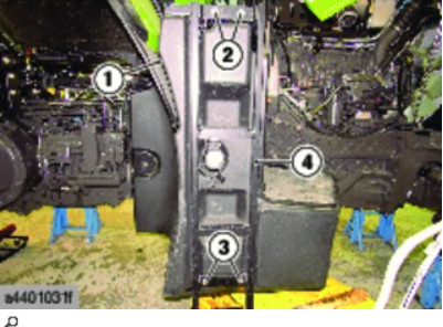
► Position a lifting table under the tank assembly.
► Undo and remove the nuts (2) and bolts (3).
► Remove the right ladder (4).
► Undo and remove the nuts (1).
► Remove the reinforcement (2).
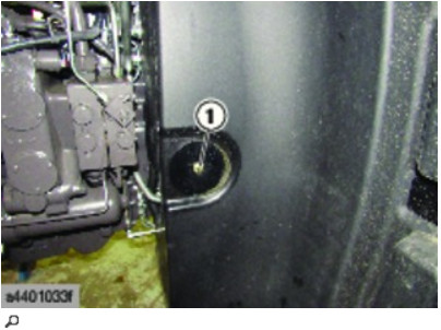
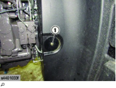
► Undo and remove the bolt (1).
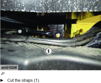
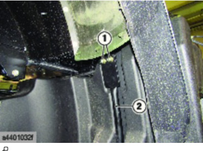
► Cut the straps (1).
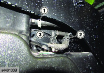
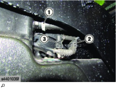
► Use the lifting table to lower the tank assembly in order to access the hoses (1) and (3) and the connector (2).
► Loosen the clamp (1) and disconnect the hose.
► Disconnect the connector (2) from the fuel gauge.
► Disconnect the urea pipe (3).
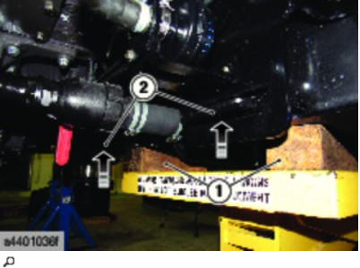
► Place wooden chocks (1) on the lifting table behind the tank assembly.
The wooden chocks are used to tilt the tank to make it easier to remove using the hinges (2).
► Lift the tank assembly to release it from the hinges (2).
► Remove the tank assembly using the lifting table.
The empty assembly weighs 120 kg.
► Remove the rest of the components remaining on the assembly as required.
Fitting
► Move the tank assembly forwards on the tractor using a lifting table.
The empty assembly weighs 120 kg.
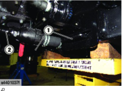
► Check that the valve (2) is correctly coupled to the hose.
► Fit the tank assembly in the hinges (1).
► Use the lifting table to lower the tank assembly in order to access the hoses (1) and (3) and the connector (2).
► Connect the urea pipe (3).
► Connect the connector (2) to the fuel gauge.
► Connect the hose and tighten the clamp (1).
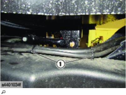
► Secure the hoses in place with the straps (1).
► Position the tank correctly.
Respect the technical specifications from the overview.
► Fit and tighten the bolt (1) to the recommended torque.
► Fit the reinforcement (2).
Respect the technical specifications from the overview.
► Fit and tighten the nuts (1) to the recommended torque.
► Fit the right ladder (4).
Respect the technical specifications from the overview.
► Fit and tighten the nuts (2) and the bolts (3).
► Remove the lifting table.
► Fit the trim (1).
► Connect the connector (1) on the work light.
► Affix the wiring harness.
Respect the technical specifications from the overview.
► Connect the hose and tighten the clamp (1) to the recommended torque.
► Connect the pipe (2).
► Remove the special tools (3).
► Open the valves (4).
► If necessary, fill up with fuel.
► Check for fuel leaks.
► Fit the protective panel (2).
► Fit and tighten the nuts (1).
► Fit the rear right-hand wheel.
► Perform an operating check.
More repair case for CLAAS,please refer to CLAAS Trouble Repair