This instruction show you guide on how to measure main pump flow 3 pumps for Kubota U48-4 U55-4 excavator.
Related Contetns:
2022 Kubota Takeuchi Diagmaster v22.08.01 v4.1.2 Software Free Download
Kubota DST-i Diagnostic Adapter
Kubota EPC Spare Parts Catalogue 2021.06 Download
Measurement preparation
1.Place the mini excavator on flat, hard ground, lower the bucket and the blade, and stop the engine.
2.Follow the chapter “Releasing Hydraulic System Pressure” and release pressure in the hydraulic lines.
3.Use a vacuum pump and attach a pressure gauge to the pressure measurement port.
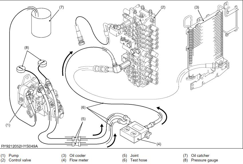
If measuring P1 & P2 flow (combined flow)
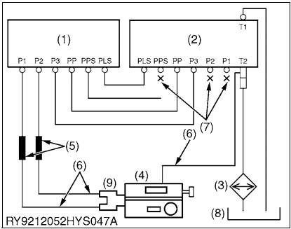
1.Disconnect the control valve side of the P1 & P2 hoses and plug the control valve’s P1 and P2 ports.
2.Connect the P1 & P2 hoses and the test hoses and connect them to the IN side of the flow meter. (Combine the flows with an adapter)
3.Disconnect the hose connecting the 2-way valve and the control valve (T2) on the control valve (T2) side and plug the disconnected hose.
4.Connect the control valve (T2) and the OUT side of the flow meter with a test hose.
5.Disconnect the control valve side of the PPS hose and plug the control valve’s PPS port.
6.Place the PPS hose in an oil catcher.
7.Remove the vacuum pump.
8.Bleed the pump of air and make sure there are no oil leaks in any of the pipes.
If measuring P3 flow
1.Disconnect the control valve side of the P3 delivery hose and plug port P3 of the control valve.
2.Connect the P3 delivery hose and the test hose and connect it to the IN side of the flow meter.
3.Disconnect the hose connecting the 2-way valve and the control valve (T2) on the control valve (T2) side and plug the disconnected hose.
4.Connect the control valve (T2) and the OUT side of the flow meter with a test hose.
5.Disconnect the control valve side of the PPS hose and plug the control valve’s PPS port.
6.Place the PPS hose in an oil catcher.
7Remove the vacuum pump.
8.Bleed the pump of air and make sure there are no oil leaks in any of the pipes.
Measurement
1.Hydraulic oil temperature of 50 ± 5 °C (122 ± 9 °F).
2.Open the loading valve of the flow meter and start the engine.
Set the engine speed to maximum, gradually close the loading valve of the flow meter, and measure the flow and engine speed at each pressure level.
3.Perform the measurement 3 times, take the average and use this as the measurement value.
(Pump performance inspection procedure)
The pump performance inspection is placing a specified pressure load on the pump discharge and performing measurement at a specified engine speed to check the volumetric efficiency.

1.The pump volumetric efficiency is proportional to pump rotational speed and inverse proportional to load pressure so set the engine speed at maximum speed for the test.
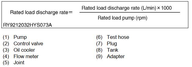
2.Volumetric efficiency is the ratio of the discharge amount per revolution (cc/rev) at a specified load and the theoretical discharge amount (calculated value). The specified load is the main relief set pressure.
3.The measurement value of the discharge flow at the specified load must be corrected to one pump revolution because the rotational speed of the pump is reduced from its normal speed.
Pilot pressure
Pilot Primary Pressure Measuring Procedure
1.Place the machine on firm, level ground, lower the bucket and blade to ground level, and stop the engine.
2.In accordance with “Releasing Residual Hydraulic System Pressure” in this manual, release pressure from the hydraulic line.
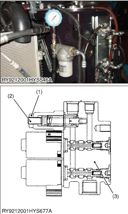
3.Remove the plug from the adapter on the pilot filter inlet side, and attach a pressure gage.
4.Start and idle the engine, and check that there is no oil leakage when the machine’s lock lever is released.
5.Raise engine speed to maximum rpm, and measure pilot pressure under no load. Perform the measurement three times,determine the average value, and take this as the measured value. Conduct at oil temperature 50 ± 5 °C (122 ± 9 °F).
Pilot Primary Pressure Adjustment Method
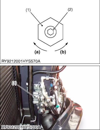
1.Loosen the relief valve lock nut (1) or the unload valve (3). Use a hexagonal wrench to turn the adjuster screw (2), and tighten the lock nut.
2.After adjusting, check the set pressure.

Pilot Secondary Pressure Measuring Procedure
1.Place the mini excavator on flat hard ground, lower the bucket and the blade, and stop the engine.
2.In accordance with “Releasing Residual Hydraulic System Pressure” in this manual, release pressure from the hydraulic line.
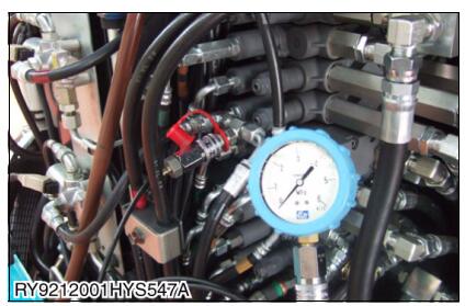
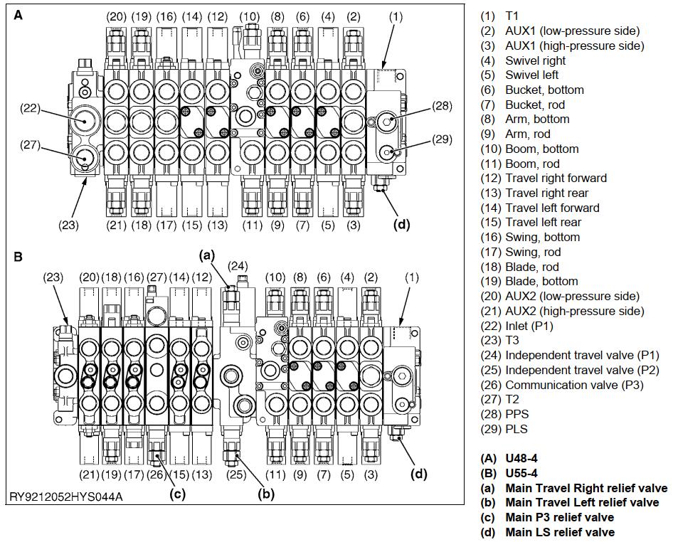
3.Fit a T-joint to the pilot port on the control valve side to be measured, and attach a pressure gage.
4. Start and idle the engine, and after checking that there is no oil leakage.
5. Operate the measuring lever after raise engine speed to maximum rpm, and take the pilot pressure reading at full throttle.
6.Perform the measurement 3 times, take the average and use this as the measurement value.
Conduct at oil temperature 50 ± 5 °C (122 ± 9 °F).
More repair case for Kubota,please refer to:Kubota Trouble Repair