This function requires all connectors to be disconnected from all electrohydraulic valves on the tractor.You are advised to use this function when adding or removing:
One electrohydraulic valve at the rear of the tractor, or
The electrohydraulic valves at the front of the tractor, or
The front linkage electrohydraulic valve.
Preparations:
Important:
For modifications to the hydraulic configuration, the label codes for the linkage controller must be updated.
Procedure
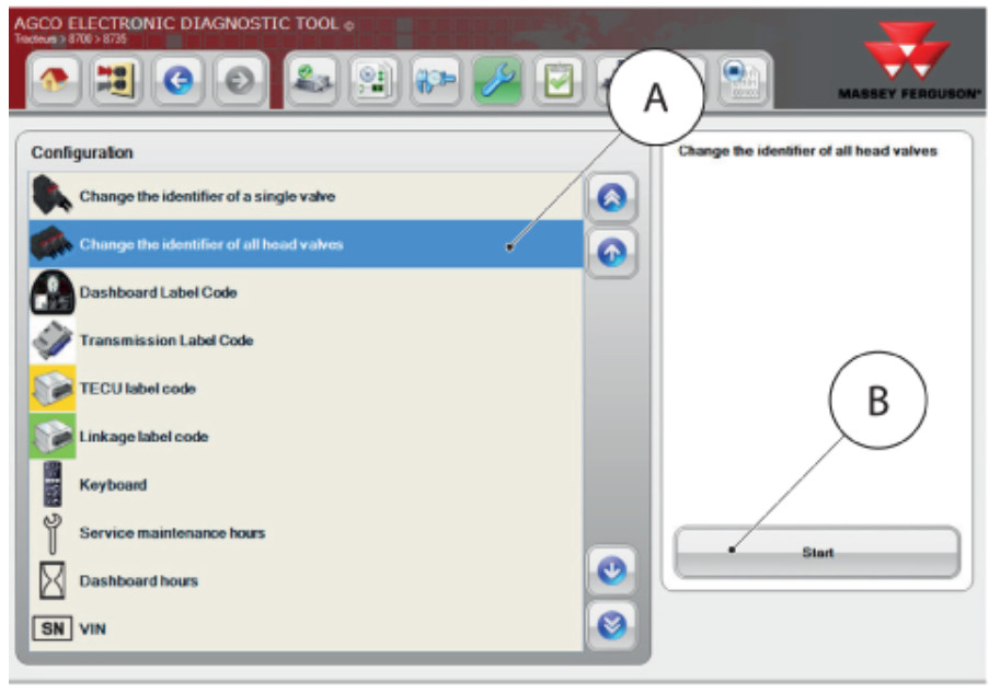
1 Select “Change the identifier of all head valves” A then “Start” B
2 Select “the maximum number valve connected on the bus” C

3 Select the maximum number of electrohydraulic spool valves at the front of the tractor D
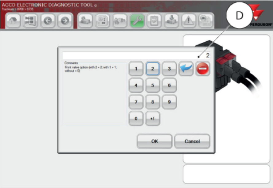
No electrohydraulic spool valves at the front = 0
With 1 electrohydraulic spool valve at the front = 1
With 2 electrohydraulic spool valves at the front = 2
4 Specify whether the tractor has a front linkage E
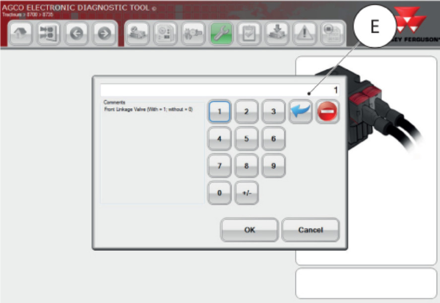
Without front linkage = 0
With front linkage = 1
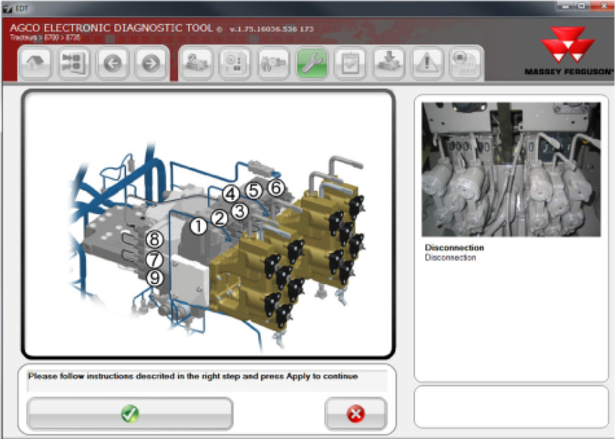
5 Disconnect all electrohydraulic valves from the tractor then “Validate” F
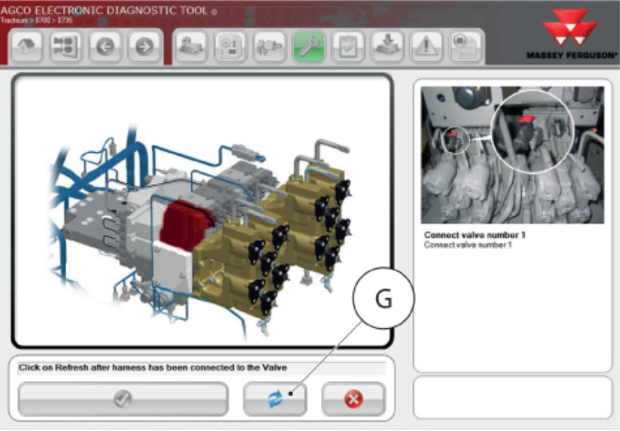
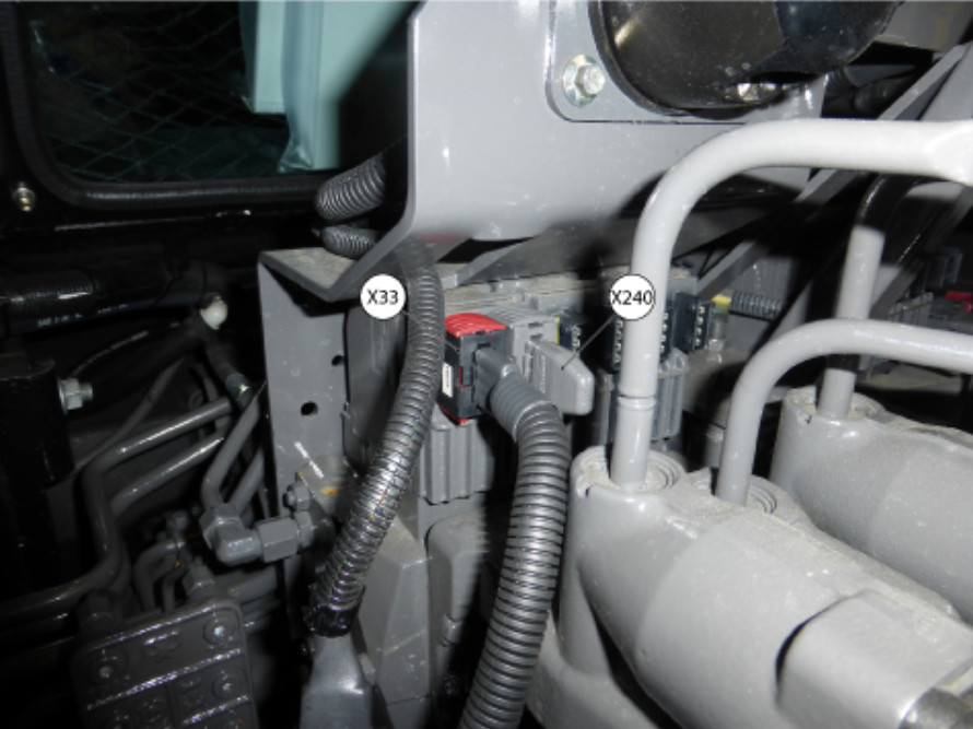
6 Connect rear electrohydraulic spool valve no. 1 using connector X33 – Connector for the electrohydraulic spool-valves supply and X240 – Termination connector for an electrohydraulic spool valve (120-ohm resistor).Select “Refresh” G once the connection to valve no. 1 has been established
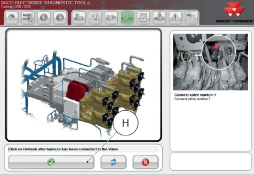
7 The following message appears: “Auxiliary spool valve no. 1 is correctly configured”. Press “Validate” H to move on to the next electrohydraulic valve.When changing the identification number of the valve, it may be necessary to switch off the ignition.
8 Repeat the above configuration steps for all the valves, following the procedure set out in the diagnostic tool and the sequence of electrohydraulic spool valves.
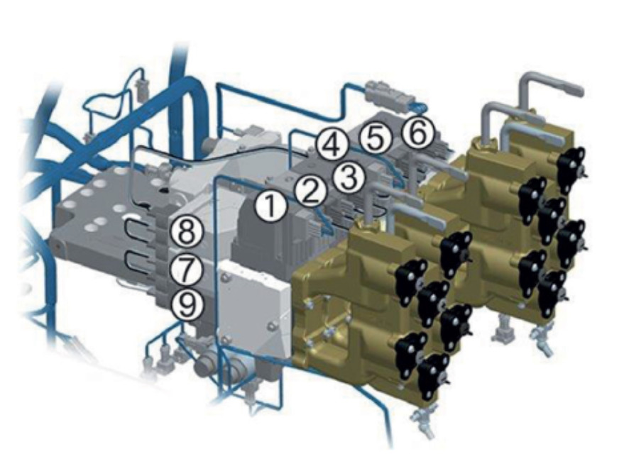
Rear spool valve no. 1 = 1
Rear spool valve no. 2 = 2
Rear spool valve no. 3 = 3
Rear spool valve no. 4 = 4
Rear spool valve no. 5 = 5
Rear spool valve no. 6 = 6
Front spool valve no. 1 = 7
Front spool valve no. 2 = 8
Front linkage valve = 9
9 Once the procedure for configuring the valves is complete, reconnect all the electrohydraulic spool valves for the tractor to their respective connectors/harnesses
AGCO EDT Electronic Diagnostic Tool 1.128 Diagnostic Software