This instruction show you guide on how to disassembly Volvo Penta D1-30 engine short block.All procedures also apply on Volvo Penta D1-13 A, D1-20 A, D1-30 A, D2-40 A Engine.
Related Contents:
2018 Volvo Penta VODIA5 5.2.50 Diagnostic Software Free Download
Volvo Penta EPC 6 2023 2016 Offline Free Download
Procedures:
Empty the oil and water out of the engine. Lift the engine with a suitable lifting device. Installing the engine fixture, please refer to “Engine fixture, fixing”.
WARNING! Observe the greatest possible cleanliness in work on the fuel system. Watch out for fuel spillage, diesel oil is hazardous on repeated skin contact.
IMPORTANT! Observe the greatest possible cleanliness, to avoid getting dirt in the fuel system.
Plug the unions in the fuel system with suitable protective plugs, such as kit no. 885510.
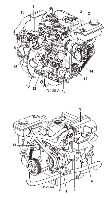
1.Remove the induction silencer (1).
2.Undo the expansion tank (2) and its bracket. Remove all coolant hoses (3) with brackets.
3.Remove the electronic box (4) complete with cable harness. Undo the engine speed sensor (5).
NOTE! Note the way that the cable harness is clamped before removing it.
4.Remove the alternator (6) with bracket, starter motor (7) and the left-hand engine mounting (8).
5.Remove the heat exchanger/exhaust manifold (9),sea water pump (10), coolant pump (11) with spacer (D1-13).
6.Remove the oil pressure monitor (12), dipstick (13) and oil pressure pipe (14) from the cylinder head.
7.Remove the fuel filter bracket (15) with anchorage,feed pump (16) and feed hose by the union (17) for the injection pump. Leave the fuel hoses between the fuel filter, feed pump and union in place.
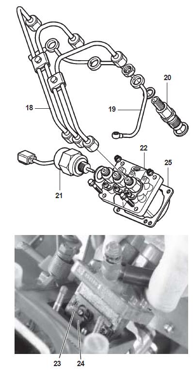
8.Remove the fuel supply pipes (18) between the fuel pump and injector, use the nut underneath the fuel return pipe to avoid kinking the pipe. Remove the fuel supply pipes and put them on a clean, dry surface.
9.Remove the return fuel pipe (19) and injectors (20).
10.Unscrew the stop solenoid (21). Remove the injection pump (22). Remove the fixing screws and nuts on the pump. Turn the stop lever clockwise and carefully lift the pump, to make the lock clip on the regulator arm accessible.
Remove the lock clip (23) and free the regulator arm (24).
IMPORTANT! Be careful when disassembling the injection pump, avoid damaging or bending its lever.
NOTE! Save the shim/gasket (25) beneath the injection pump flange. Use the same thickness of shims when re-installing, unless the camshaft, engine block or injection pump has been changed.
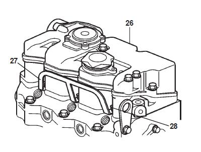
11.Remove the valve cover (26), bus bar (27) and glow plugs (28).
12.Remove the lower part of the valve cover (29) with the integrated rocker arm bridge. Start by unscrewing the two screws (30) on the edge, then undo the rocker arm bridge nuts (31) one turn at a time until the load on them has been relieved.
13.Prepare a stand, marked with cylinder numbers. If the valve caps, push rods and valve lifters are to be re-used, they must be put back in their original places.
Lift the push rods and valve caps out and put in them in number sequence in the marked stand.
17.Undo the screws (32) in the opposite sequence to when they are tightened, please refer to “Technical Data”. Remove the cylinder head.
18.Remove the valve lifters out of the engine block with a magnetic pen, part no. 885 822. If the valve lifters are to be re-used, they must be put back in their original places.
NOTE! The D1-20 and D2-40 engines have some valve lifters which are chamfered off.
19.Remove the flywheel cover (33) and flexible coupling(34).
23.Undo the center nut (35) on the pulley. Remove pulley (36), use special tool 885 820. Use the flywheel as a counterhold. Remove the Woodruff key from the crankshaft.
20.Remove the flywheel (37).
22.Remove the inner flywheel housing (38) and rear crankshaft seal.
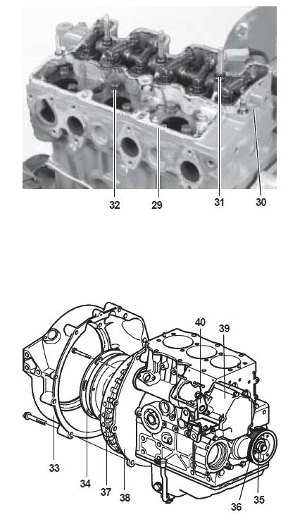
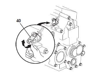
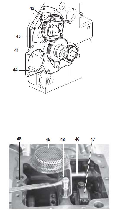
23.Remove the timing gear cover (39). Load the stop arm (40) so that the springs on the inside of the housing do not come out of position or spring out.
24.Remove the idler wheel (41) circlip. Save the sleeve washer, spring and shims.
Lift away the idler wheel, complete with cover and oil pump. Also remove the thrust washer behind the idler wheel.
25.Remove the locking plate (42) screws. The screws are accessible behind the holes in the camshaft gear.
Lift out the camshaft (43), complete with gear and regulator weights.
NOTE! Be careful to avoid damaging the bearings, bearing tracks and camshaft lobes.
26.Remove the timing gear plate (44) with gasket.
27.Turn the engine over and remove the sump, together with the external oilpipe. Remove the oil strainer (45) and oil suction pipe (46). Remove the oil pressure reduction valve.
28.Scrape away the line of carbon at the top of the cylinders, to facilitate removal.
Remove the big end bearing caps (47) and press the pistons out.
NOTE! Check the markings on the big end bearing caps.
29.Remove the locking screws (48) which hold themain bearing caps. Lift the crankshaft out carefully,complete with caps, backwards.
NOTE! Tape the crankshaft gear to protect the bearing surfaces in the block during disassembly.
